how to draw a 3d house in autocad 2010

This is a guest mail by Andreea Georgiana. She is a CAD enthusiast who likes using the ability of Computer Aided Design to create absurd useful designs, from conception to 3D printing. She has a 21-twenty-four hour period AutoCAD course at tutorial45.com.
She says, "Existence able to employ Estimator Aided Pattern software to bring your ideas to life is one of the things I totally disagree simply engineers should exist able to do. With the numerous advantages of being able to move past the level of a 3D model to actually having the model 3D printed, anyone should consider learning at to the lowest degree the nuts of modifying a CAD model.
"Equally a CAD hobbyist, wife and female parent, I accept establish many cases where a customized solution designed myself has solved a problem in the exact manner I wanted, thanks to the power of CAD and 3D printing. Y'all can notice some free tutorials hither."
* * * * *
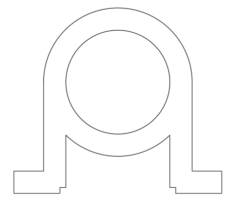
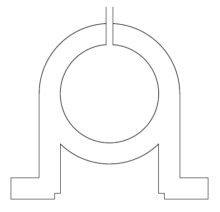
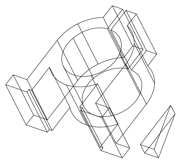
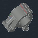
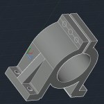
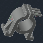
Before I start, hither are second and 3D images of the model you'll draw in this tutorial,
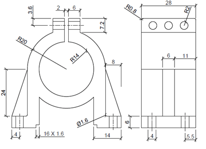
Use the images in a higher place to help you in completing the 3D model.
Phase 1: Draw the pipe (circles) and legs (lines)
Make certain the Quadrant and Midpoint in Objects SNAP settings are on. The upper parts of the legs are snapped to the left and correct quadrants of the model. Later, yous'll apply the Midpoint OSNAP.
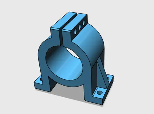
And so follow these steps, following the paradigm to the correct and below:
- Describe 2 concentric circles with R20 and R14.
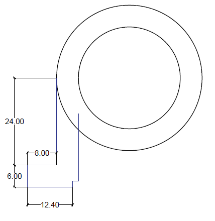
- Draw a vertical line downwardly from the left quadrant of the outer circle 24 units long
- Draw a horizontal line of viii units toward the left using the lower end of the vertical line you just drew as the starting point.
- Draw a vertical line of half-dozen units downwardly from the ending point of the previous line
- Depict a horizontal line of 12.4 units rightward from the ending point of the previous line
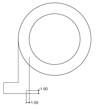
- Draw a vertical line of ane.6 units upward
- Draw a line of 1.half dozen units to the correct

At present follow these steps to trim and mirror the model:
- Utilise the TRIM command to remove the unnecessary part of the circle. Use the 2 lines that meet the circle every bit the cut edges and the office of the circle between them as the object to trim.
- Now mirror this left side using the center of the circumvolve to create the similar shape on the right side of the circle.
- Trim it to complete this footstep using the TRIM command. Y'all should end up with an image similar to the one below
Phase 2: Pause the circles at the top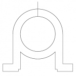
Follow these steps:
- Utilize the Upper quadrant of the inner circle to depict a vertical line that crosses the outer circle. The length of the line does not matter.
- Use the First command with the First dimension fix to 1 units to depict ii lines on each side of the original line.
- Now delete the central line.
-
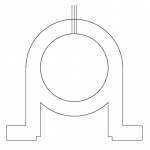 Employ the EXTEND command to extend the remaining lines to the inner circle. Yous might need to zoom in to notice that they don't actually intersect with the circumvolve.
 - Use the TRIM control to trim the two circles as shown in the paradigm below. Apply the lines equally the cutting edges.
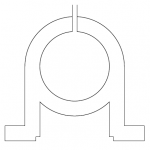
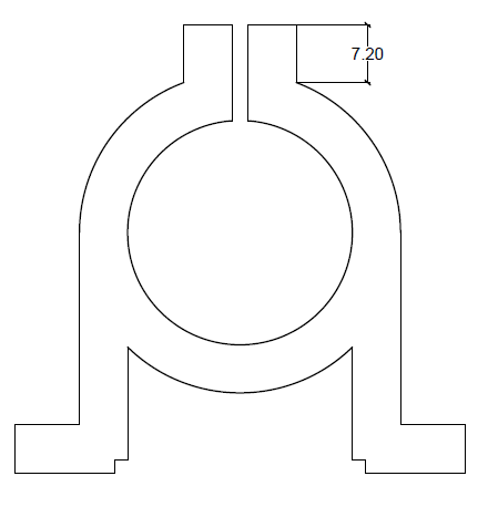
Phase 3: Add the peak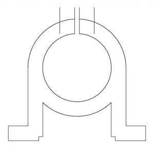
Follow these steps:
- Use the OFFSET command to offset the left line to the left and the right line to the right with an offset distance of half-dozen units.
- Trim the new outer lines using the outer circle as the cutting edge., So trim the meridian part of the outer circle using the outer lines as the cutting edge.
- You desire the outer lines to exist seven.2 units long, every bit shown on the image below and and then and y'all demand to close the caput using a horizontal line.
- One style to exercise this is to first the LINE control, type from on the command line and gear up the starting time to 7.2, moving your cursor upwardly. The draw the LINE horizontally to the left until it intersects the outer vertical line on the left. Then trim the parts of the line that extend past the new horizontal line and trim the part of the horizontal line between the 2 inner vertical lines.
Phase 4: Add the bracing (triangle)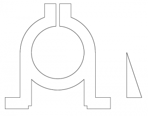
Blueprint the petty triangle on the side of the model by drawing a vertical line of 24 units, a horizontal line of viii units, and then closing the triangle. For at present, put information technology out to the side, separated from the chief model. You can draw on acme of the existing lines to start, close the triangle, and and so select each of the 3 lines and movement them to the right.
Stage 5: Set up for 3D conversion
Utilise the REGION control and select everything on the cartoon area to class 2 regions.
At this betoken, if you aren't using a 3D workspace, you should switch to ane. Click the piffling arrow to the right of the Workspace Switching icon on the lower-correct corner of the AutoCAD window and cull 3D Modeling.
Phase vi: Modify the view and extrude to 3D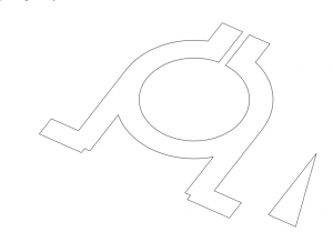
Navigate in 3D using Free Orbit. Click on Free Orbit in the navigational bar at the correct, click on your mouse, hold, and motility until you get a 3D view something like the i y'all encounter here. You can drag on the "orb" and its circular handles to get the right view. A keyboard shortcut might piece of work for you: Agree downwardly the Shift cardinal and click and elevate with your mouse's middle (gyre) push.
Use the EXTRUDE command to extrude the model by 28 units and the triangle past 6 units.
On the Visualize tab, in the Visual Styles panel, click the Visual Styles drop-down and choose Shades of Grayness.
Phase 7: Gather the model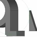
Follow these steps:
- Using the View cube at the upper correct of the AutoCAD window, switch to the Top view (or go to the Visualize tab, Views panel, and click Top.)
- Use a regular 2nd mirror control to mirror right triangle so that you lot take i on each side of the 3D model.
- Now use 3D orbit once more to go a view like you lot encounter hither.
-
- Use the Movement control to move the triangle from the midpoint of its upper border to the midpoint of the 3D line on the circumvolve quadrant. every bit shown in the prototype here.
- Plow the view over again and then you can come across the left side of the 3D model and move the left triangle in the same way.
- Start the Spousal relationship control, select the three objects, and printing Enter.
Yous have just merged the 3 object to form 1.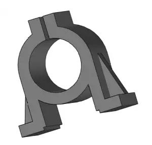
 Phase 8: Add mounting holes to the base
1 nice thing with AutoCAD when you model in 3D is that yous can still use the power OSNAP and draw second lines that volition assistance yous design in 3D.
Follow these steps:
- View the model and then you tin create the diagonal lines shown on the image at the right. Apply the Endpoint OSNAP for the start and end points. Yous'll have to change the view several times as you draw the lines.
- Create circles using the midpoint of each of the lines you just created as the center and a radius of 2.
- Extrude the circles down so the height goes completely through the model. You lot can select and extrude them all at once.
- Subtract the 4 cylinders from the model. Start the SUBTRACT control, select the model and printing Enter, so select all of the cylinders and press Enter.
- Delete the diagonal lines.
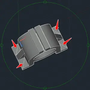
Phase nine: Fillet the sharp corners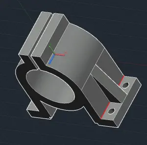
The FILLET command volition help you round some of the precipitous edges. Follow these steps:
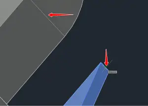
- Select the edges with the ruby-red mark. To make it easier to select just the edge, on the Dwelling tab, in the Option panel, cull Border from the Filter drop downwards. (You might see No Filter, Vertex or Face up before you make this pick.)
- Use the FILLET control to round their shape with a dimension of R = 0.8 units. To FILLET, start the command, select the appropriate edge, enter 0.eight, and press ENTER ii times.
- Repeat the process with the opposite edge.
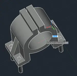
Phase 10: Add holes in the meridian
This is the concluding phase. Follow these steps:
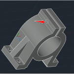
- Depict the line shown on the epitome beneath using the midpoints of the two edges.
- Create a circle of radius 2 units using the eye of the drawn line.
- Delete the line you lot just drew and create 2 lines using the quadrant of the circumvolve and 2 edges you previously used. You might accept to rotate the model to find the object snaps.
- Now, use the center of those lines to create ii circles of radius 2.
- Delete the lines and extrude the three circles using the EXTRUDE control and brand sure they go all the way through the model.
- Decrease those cylinders from the 3D model using the SUBTRACT command.
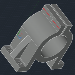
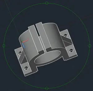
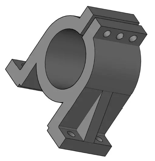
Congratulations!
You should cease up with the following model. You might demand to FILLET few more edges to take your model wait identical to the model on the exercise. I hope this has been helpful to you!
Andreea hasa 21-lesson course hither that yous might find valuable.
- Writer
- Recent Posts

Ellen Finkelstein is the author of the acknowledged AutoCAD & AutoCAD LT Bible, which started with R14. Ellen has written extensively on AutoCAD, including manufactures for Autodesk's website and features for AutoCAD'due south Help system. Ellen'south first book was AutoCAD For Dummies Quick Reference.
Source: https://allaboutcad.com/tutorial-create-3d-model/
Postar um comentário for "how to draw a 3d house in autocad 2010"